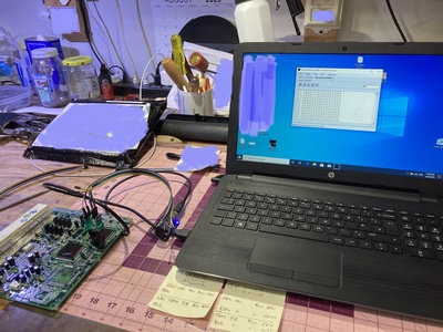
A great guy on facebook just walked me through flashing my ECU immobilizer, to allow programming a complete set of new keys (3). It took a Flashcat PC board, one clip thingie and a few hours fighting with drivers and firmware uploads, and... ta da! I have three keys that will start my car now!
After ordering the flashcat board from Australia, I discovered it’s available on Amazon prime! Geesh! So I overpaid about $20 and waited three weeks unnecessarily. After lots of hand holding from my (new) friend, I now have the tool to flash the ECU myself.
Total cost for me was about $75. You can probably duplicate the parts for about $50 by ordering from amazon. If there’s interest I will write up the whole process so it can be duplicated.
I have an early draft of the process below. I will not maintain it with edits and corrections. Instead, I'm keeping one document updated on google documents. I hope the link works for folks.
I make Amateur Armrests - see the Commercial Forum. I also have SMT repair seals available.
MR2 Spyder Immobilizer Flash Procedure
(edit #1)
This is an early draft of the process below. I will not maintain it with edits and corrections. Instead, I'm keeping one file updated on google documents. I hope the link works for folks.
Background:
Spyder keys have an RFID chip molded into the plastic handle. There is a coil buried in the plastic trim surrounding the ignition key slot (on the dashboard), that communicates with the RFID chip in the removable key. The spyder ECU must be programmed to recognize the RFID chip in each key, before it will allow the fuel injectors to fire. If the chip is not programmed (and the key is cut to work in the ignition switch) the engine will turn over but it will never run.
The ECU immobilizer chip mounted to the ECU circuit board keeps track of the ignition keys that are registered to the ECU. Typically there are two Master keys and one Valet key. The Master keys will open all the locks on the car, plus start the engine. The Valet key is cut differently allowing access only to the ignition switch - but not the glovebox, engine compartment lock, or cubby door locks. The Valet key will allow starting the engine.
Problems result when the master key(s) are lost. Techstream software will allow you to program additional keys, however you must have one master key. My used spyder came with only a valet key so I was stuck.
I think the dealer price for “flashing” the computer to accept new keys is expensive. Locksmith stores will supposedly flash the computer for $50 and up. I didn’t pursue that avenue since I prefer having the tools to do stuff like this myself. And the locksmith wanted me to schedule a time, then wait an hour or more while they did the work at their shop.
Process:
Buy a small circuit board, an IC test clip (about $50 on amazon)
Download and install a program and drivers (free) onto Windows PC
Remove the ECU
Re-program the immobilizer chip on the ECU board
Reassemble, and the ECU will accept any three keys
Procedure:
1.1 Buy stuff
Order “Flashcat USB Memory Programmer” (Currently available on Amazon Prime $46)
Order “SOIC8 SOP8” IC Test Clip from Amazon (Currently available on Amazon Prime $7)
1.2 Install
Download Flashcat software and drivers from “embeddedcomputers.net”.
They are all bundled in a zip file.
Extract the files and store them all in one folder.
1.3 Remove the ECU
Disconnect the battery. Remove the ECU from behind the driver’s seat. It’s partially hidden under a cardboard piece. Four 10mm nuts. Unplug the four big connectors. I push the release tab with a screwdriver, then gently pry the connector loose.
Open up the ECU case (four phillips screws)
Remove the ECU circuit board (two phillips screws)
1.4 Flashcat board set up
When the flashcat board arrives you have to install drivers on your PC.
Follow the documentation in the “Manual” folder in the flashcat download.
Note: Windows 10 will generate an error “Windows found drivers but encountered an error while attempting to install...check with the device manufacture”. This is a lie. Windows 10 has a driver protection block built in. You must disable it before you can install the driver files. You need to disable “Device Driver Signing”. Google the process. It involves changing the startup settings, advanced options, startup options, and restarting the computer 2-3 times. The protection will reset automatically after you have installed the drivers and restarted the PC.
Next you need to verify the correct firmware is installed on the flashcat board.
Open the flashcat program, and hit the “console” tab.
Check at the bottom for the messages “Disconnected from Flashcat USB Classic device”, and “software requires firmware version 4.5.1”. If you see this (like me) then you need to install the newer firmware included with the downloaded files.
Follow the Manual instructions for “bootloader” - basically throw one tiny dip switch to the “off” position. Click on the new firmware file in the downloaded file. Throw the switch back to the “on” position.
If everything is working, the flashcat board will have one red and one blue LED light illuminated.
1.5 Flashcat board hookups
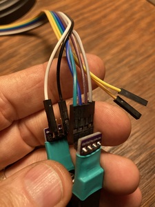
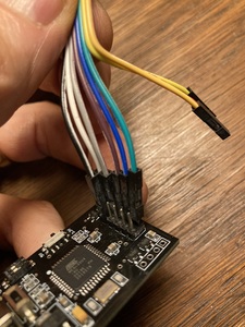
You need to plug in six wires on the board, and six wires on the clip.
See the photographs.
Don’t confuse the gray and white wires (look at the sequence of wires in the strip)
1.6 ECU hook up
Find the immobilizer chip on the ECU circuit board.
Clean the protective varnish off the 8 tiny wires.
I scratched them with a pocket knife, then scrubbed with a little “wax and tar remover”. I’m sure there are many ways to get them clean.
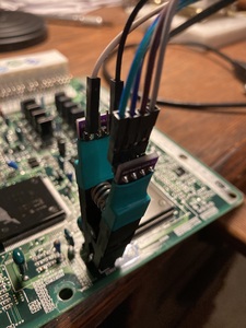
Hook the spring loaded clip onto the immobilizer chip as shown in the photos. Don’t get it backwards - the four wires go near the edge of the ECU board.
1.7 Flashcat program settings
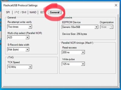
Set all the pulldown options like shown in the photos.
Don’t dick around with the other settings, leave them as they are preset.
1.8 Rewriting the immobilizer
It’s a good practice to copy the existing codes from the chip before you modify them. If something goes wrong, you can copy the original settings back onto the chip.
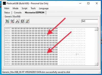
Edit the hex codes on the immobilizer, changing them all to “00” EXCEPT the four cells shown in the photos. You only need to do this once, since you can save the zero’d out settings in a file, and use it again in the future. (Avoids you having to type all those zeros)
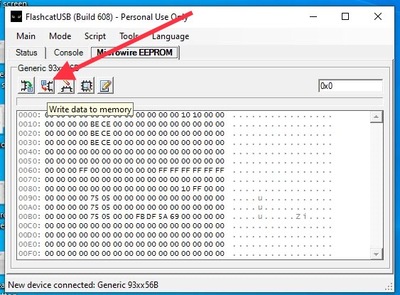
Write your edits to the chip.
1.8 Reinstall and program keys
Now the ECU is “virginized”, and it will be ready to accept new keys with no hassle.
It is a very quick process to program up to three keys.
Reinstall the ECU into the car, hook up the battery and get all your keys laid out.
Insert any key, and look for the immobilizer LED on the dashboard to go solid red (not flashing)
This is “program mode”.
Follow the procedure below, inserting your keys for 5 seconds each, one after the other.
I did it twice and never got really good at understanding which one gets assigned as “valet” key.
But they all start the car, and I ended up with two Master keys.
1.9 Programming keys
Here is the published process.
Key Programming
When reconnected to the car, the ECU will be in Auto-Programming Mode and will accept new keys as per the following procedure:
- Briefly insert any key into the ignition lock cylinder and remove immediately. The security light should illuminate and remain on.
- Insert the first transponder key into the ignition lock cylinder for registration, DO NOT TURN ON. The Security light may blink indicating it has accepted the key. After 3-5 seconds remove the first key from the ignition. The Security light should remain on indicating you’re still in programming mode.
- Insert the Second transponder key into the ignition lock cylinder for registration, DO NOT TURN ON. The Security light may blink indicating it has accepted the key. After 3-5 seconds remove the first key from the ignition. The Security light should remain on indicating you’re still in programming mode.
- Insert the third transponder key into the ignition lock cylinder for registration, DO NOT TURN ON. After the Security light goes off remove the third key from the ignition. The security light should extinguish and then commence to blink regularly.
- Wait 30 seconds for the programming cycle and programming mode to close.
The 1st two keys are programmed as Master keys and the 3rd key a Valet key.
To Test, when a Master key is inserted into the ignition lock, the security light should stop blinking straight away.
If a Valet key is inserted, the security light will remain on (not Blinking) for 2 seconds and then go out.
If the Security light does not stop Blinking, with a key inserted, that key is not programmed to the car.
I make Amateur Armrests - see the Commercial Forum. I also have SMT repair seals available.
This is an early draft of the process below. I will not maintain it with edits and corrections. Instead, I'm keeping one file updated on google documents. I hope the link works for folks.
PICTURES
Hook up wires connecting the IC Clip to the Flashcat board.
Attach the IC clip to the immobilizer chip. The four wires go towards the edge of the ECU board.
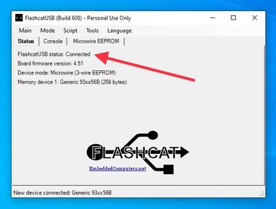
Launch the Flashcat program and verify it is “connected” to the chip.
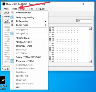
Verify the Mode tab settings are all correct.
Set all the Protocol “General” settings as shown. Don’t dick around with the other tabs (SPI, SWL, NAND etc)
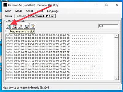
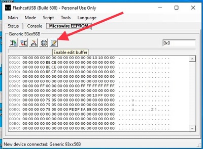
Look at the gibberish in your immobilizer, prior to flash.
Save a copy of these settings, in case something goes awry.
When the little box with 0x0 and 256 comes up, just hit okay.
Change the hex codes all to “00” except the four that are marked. Leave them alone.
To avoid editing all these hex codes
to “00” every time you flash an ECU, you can do it once, then save the binary file to use in the future. It seems best to leave the pre-assigned file name alone, and add your own suffix to the file name.
If you have previously saved a “00” file, instead of typing all those zeros, you can just “Write the file” to the chip memory.
Th th that’s all folks.
Close the Flashcat program and unplug the Flashcat board.
Then unclip the IC clip.
Go install the flashed board in the car.
I make Amateur Armrests - see the Commercial Forum. I also have SMT repair seals available.
Always interested in ways to bypass security... 😎
Mono Craft GT-300 with a few upgrades...
This is an early draft of the process (above). I will not maintain it with edits and corrections. Instead, I'm keeping one file updated on google documents. I hope the link works for folks.
I make Amateur Armrests - see the Commercial Forum. I also have SMT repair seals available.
Xxx
I make Amateur Armrests - see the Commercial Forum. I also have SMT repair seals available.
OMG! Y'all amaze me with the stuff you know! I am in awe of your greatness. Thank you for all of your time and energy to write-up this procedure and take/post photos.
OMG! Y'all amaze me with the stuff you know! I am in awe of your greatness. Thank you for all of your time and energy to write-up this procedure and take/post photos.
Thanks Mush! I did spend a good amount of time writing this up. The technical content however is not mine - I'm just the scribe. I have zero knowledge of EPROM chips, PC boards, programming etc.
I make Amateur Armrests - see the Commercial Forum. I also have SMT repair seals available.
And I thought all you did was make arm rests... 👍 👍
"Think as we think", say many Spyder owners, "or you are abominably wicked, you are a toad". After I'd thought about, I said "I will then, be a toad."
Thank you, Stephen Crane
